Contents
Introduction
Routing embodies a process where network traffic journeys are orchestrated. In this mechanism, a packet’s origin and destination are dissected, steering it through a dedicated forwarding mechanism. This encompasses the management from a network interface (ingress) to another (egress).
Routing implementation is not confined to specific devices; switches, firewalls, servers, and load balancers, among others, are participants. SKUDONET stands out by implementing an exceptionally efficient and effective advanced routing system. Furthermore, it accommodates customization where required. But let’s explore the fundamental operation of a routing system and delve into SKUDONET’s approach and its advanced features.
Basics
Every basic routing system relies on a simple routing table. This table acts as a regulator, checking traffic rules against incoming packets. It assesses where the source IP is located within the packet and where the destination IP is headed. If the packet fails to meet any criteria, it’s rerouted to the gateway, allowing its journey to continue.
But what if a more sophisticated approach is needed? Imagine a scenario where packets need to be directed to different gateways based on their source addresses. Or consider situations where packets arriving within the same network require complex algorithms or a marking system for forwarding. This is where SKUDONET’s implementation comes into play, operating in the following manner.
When a packet arrives, it undergoes evaluation against a set of rules in a designated table. This set of rules determines the appropriate routing table for the packet based on its content. After the decision to forward the packet is made, it undergoes further assessment within the chosen route table before being sent to its intended destination, as indicated in the routing table.
Exploring a Basic Routing Setup
The diagram below provides insight into the decision-making process of a straightforward routing system when it comes to packet forwarding:
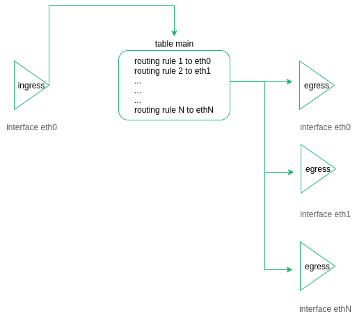
The journey begins when the packet ingress the device through eth0. The routing table then examines the packet’s destination. Subsequently, the packet is directed to a designated interface to be egressed. This operational approach is both uncomplicated and valuable.
Exploring Advanced Routing in SKUDONET ADC
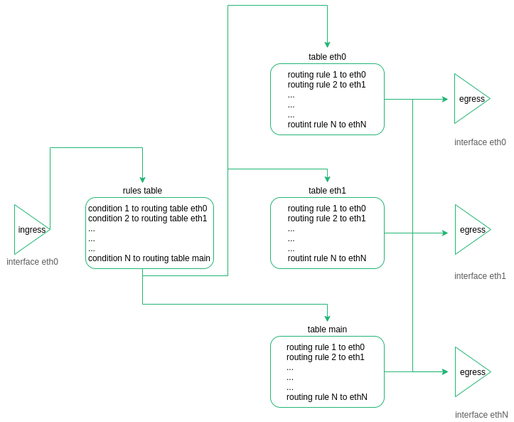
As we’ve previously mentioned, the SKUDONET ADC device incorporates a sophisticated routing system. In this setup, the packet’s course is initially determined by a process referred to as “rulerization.” Subsequently, the decision is made regarding which table the packet should be forwarded to:
The routing module of SKUDONET ADC was conceived based on the following principles:
Each network interface (NICs, VLANs, or Bonding) independently manages its own routing table and gateway.
Traffic directed at a Virtual IP (VIP) is controlled by the same routing table for both incoming (from client to load balancer) and outgoing (from load balancer to backend) traffic.
Upon reaching a farm, each packet is marked, and this marking determines the subsequent redirection of the packet.
The routing system is designed to maintain simplicity by minimizing the usage of static routes, as adding more interfaces would otherwise increase complexity.
When the ADC needs to connect to external systems, such as navigation proxies, DNS, or hotfix reviews, a dedicated table (referred to as “table main”) is employed.
Load-balanced traffic employs distinct tables from the main routing table, facilitating the separation and isolation of various traffic types.
Understanding a Practical Routing Scenario
Consider the following scenario: a SKUDONET ADC is set up with two Network Interface Cards (NICs) named eth0 and eth1.
Let’s list the routing table for NIC eth0:
ip route list table table_eth0
eth0 IP 192.168.100.10
eth0 NETMASK 255.255.255.0
eth0 Gateway 192.168.100.5
Now, let’s list the routing table for NIC eth1:
ip route list table table_eth1
eth1 IP 192.168.101.10
eth1 NETMASK 255.255.255.0
eth1 Gateway 192.168.101.5
VIP1 192.168.101.11
In the context of the main routing table, the default gateway is 192.168.100.5. You can view this information using the following command:
ip route list table main
Here’s a scenario: a client reaches a Virtual IP 192.168.101.11 within a L4XNAT farm, using port 80. This particular farm has been configured for load balancing traffic between two backend servers, namely 192.168.200.20 and 192.168.200.21.
The L4XNAT farm operates within the Local Service Load Balancing (LSLB) module. Each backend server within the farm is assigned a unique mark identifier. As a packet arrives at the VIP 192.168.101.11 on the Virtual port 80 (configured within eth1), the load balancing module adds a mark to the packet to indicate the destination. The rule system then checks this mark to determine the appropriate route table for the packet.
For instance, the l4xnat farm marks a packet with the value 201 to identify the backend 192.200.20 within the farm associated with Virtual IP 192.168.200.20 and virtual port 80. Subsequently, the rule table forwards the packet to the corresponding route table:
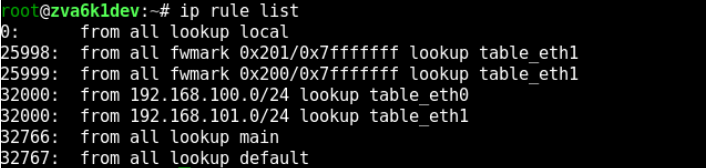
You can list the routing rules using the following command:
ip rule list
As indicated by the ID 25998, all traffic marked with mark 201 will be directed to the table table_eth1. Now, let’s examine the content of table eth1:
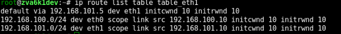
When the packet attempts to reach the backend 192.168.200.20, it is noted that this destination IP is not directly accessed. Consequently, the default gateway will be utilized, and the packet will be forwarded to 192.168.101.5 as the next hop.
Through this mechanism, the system initially marks packets to identify the destination. The advanced Routing system then ensures the proper forwarding of the packet, confirming that it reaches its intended destination.
Furthermore, the Routing system can be configured and customized according to specific client requirements. If you wish to modify the rule system, please refer to the web GUI section NETWORK > Routing > Rules. Similarly, if you intend to make changes to a routing table, please consult the web GUI section NETWORK > Routing > Tables.
