Global L4xNAT farm profile settings
The L4xNAT farm profile creates LSLB farms that operate at layer 4, which is faster than layer 7. L4xNAT farms can also handle more connections than layer 7 farms, unlike layer 7 farm profiles, which only support ports 80 and 443, L4xNAT farm profiles can use multiple ports, including port ranges.
This section provides a detailed explanation of the required commands for configuring an L4xNAT farm profile. We highly recommend using Farmguardian in conjunction with this profile to monitor the status of each backend configured on the farm, since L4xNAT farm profiles do not have any built-in health check functionality.
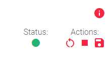
The status indicator and Actions section allows you to perform operations such as Restarting, Starting, or Stopping the farm.
Farm status indicators
The status of a farm is shown by a color:
 Green: The farm is running and all of the backends are available.
 Red: The farm is stopped or unavailable.
 Black: The farm is running, but none of the backends are available.
 Blue: The farm is running, but at least one backend is unavailable.
 Orange: The farm is running, but at least one backend is in maintenance mode.
These colors are used throughout the graphical user interface.
Basic L4xNAT farm profile settings
These settings allow you to configure the basic parameters of your L4xNAT farm profile:
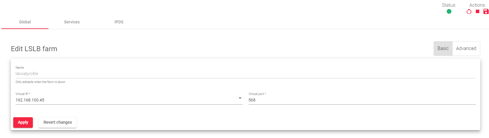
- Name: A label that easily identifies your farm service. To change this value, you must first stop the farm. Make sure that the new farm name is not already in use.
- Virtual IP: This specifies the IP address on which the farm will listen internally within the appliance.
- Virtual Port: This specifies the Port on which the farm will listen internally within the appliance.
Here is a simplified explanation of each setting:
- Name: The name of your farm profile.
- Virtual IP: The IP address on which the farm will listen for incoming traffic.
- Virtual Port: The port on which the farm will listen for incoming traffic.
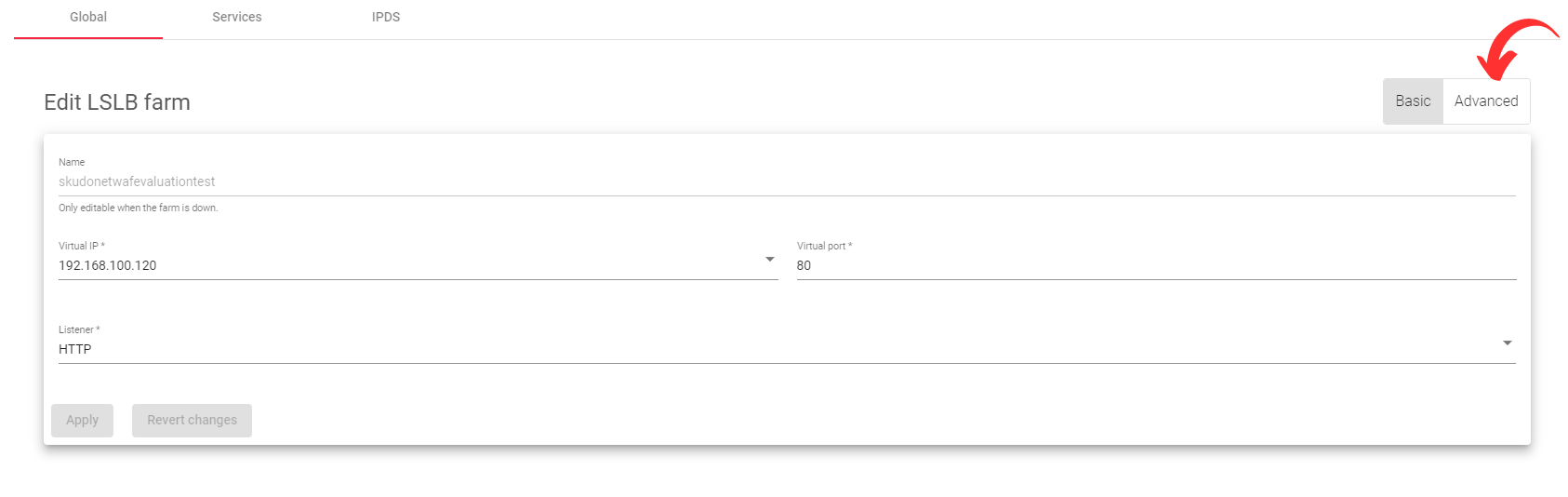
Advanced configuration
Protocol Type
This field lists all the supported protocols on the load balancer. By default, the farm uses the TCP protocol.
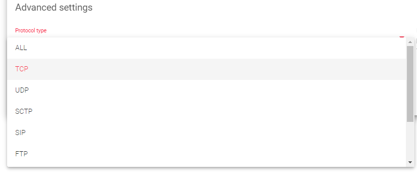
- ALL: The farm will listen for inbound connections to the current virtual IP and port(s) over all protocols. If you select this option, the virtual port will change to the default “*”, and you will not be able to edit it. So, the farm will listen through all ports.
- TCP: Enabling this option allows the farm to listen for inbound TCP connections to the current virtual IP and port(s).
- UDP: Enabling this option allows the farm to listen for inbound UDP connections to the current virtual IP and port(s).
- SCTP: Enabling this option allows the farm to listen for inbound SCTP connections to the current virtual IP.
- SIP: Enabling this option allows the farm to listen for inbound UDP packets to the virtual IP and the default port, 5060. The farm will then parse the SIP headers of each packet to be correctly distributed to the backends.
- FTP: Enabling this option allows the farm to listen for inbound TCP connections to the current virtual IP and the default port, 21. The farm will then parse the FTP headers of each packet to be correctly distributed to the backends. Two modes are supported: The Active and the Passive mode.
- TFTP: Enabling this option allows the farm to listen for inbound UDP packets to the current virtual IP and the default port, 69. The farm will then parse the TFTP headers of each packet to be correctly distributed to the backends.
- PPTP: Enabling this option allows the farm to listen for inbound TCP connections to the current virtual IP and port. The farm will then parse the PPTP headers of each packet to be correctly distributed to the backends.
- SNMP: Enabling this option allows the farm to listen for inbound UDP packets to the current virtual IP and port. The farm will then parse the SNMP headers of each packet to be correctly distributed to the backends.
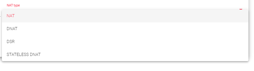
NAT Type
The NAT Type functionality within the appliance governs all the layer 4 operations. Choosing the appropriate option for your infrastructure will depend on the specific network architecture defined in your environment.
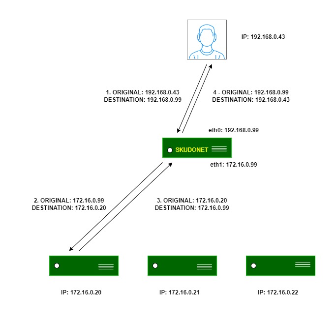
NAT: The NAT mode or SNAT (source NAT) uses the farm’s Virtual IP as the source IP address to connect to the backend servers. Therefore, the backend servers will not know the original source IP address of a web client at TCP, UDP, or any other layer 4 protocol. This way, the backend responds to the load balancer, and then the load balancer will respond to the client. This topology allows for the deployment of a one-armed load balancer (load balancing with 1 network interface).
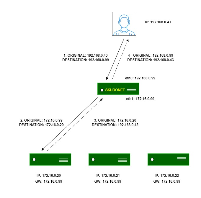
DNAT: In DNAT (Destination NAT) mode, the client IP address will be used to connect with a backend server. As a result, the backend will directly respond to the client IP. In this case, the load balancer IP should be configured as the backend’s default gateway, effectively separating the backend network from the client service network. This topology establishes transparency between clients and backends.
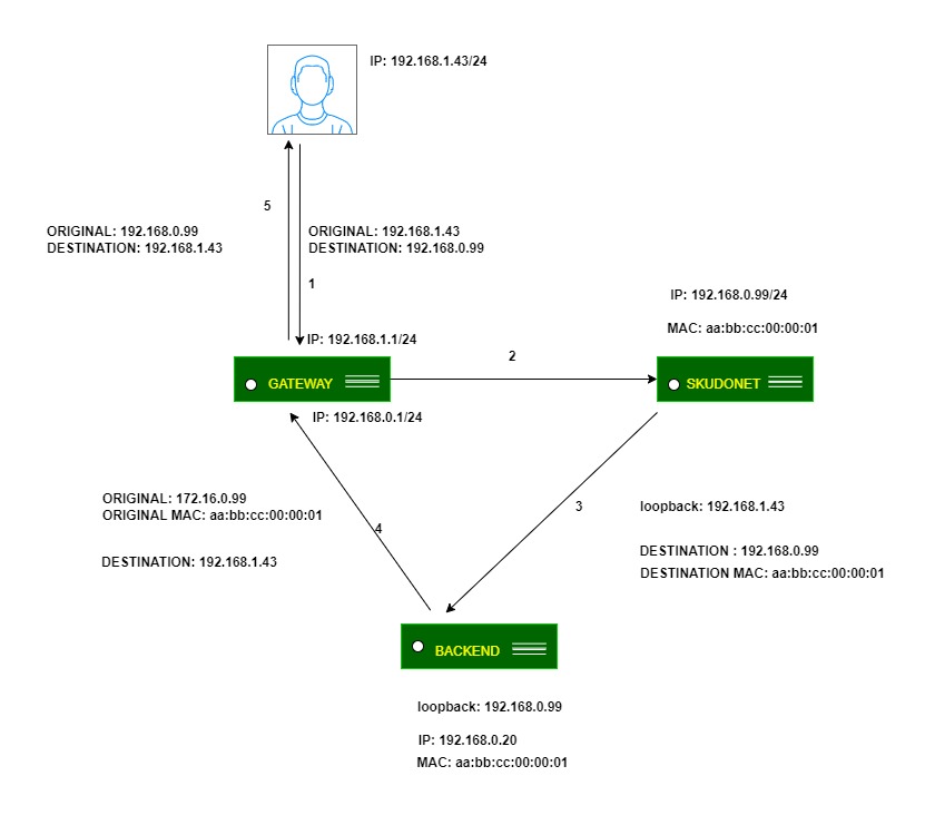
DSR: In DSR mode, the client connects to the load balancer’s Virtual IP (VIP). The load balancer then alters the Destination MAC address by changing it to that of a backend server without changing any IP address. However, all backend servers must be on the same network as the load balancer. When a backend server receives and processes the request, it directly responds to the client, bypassing the load balancer.
In simpler terms:
- Protocol Type: This setting tells the load balancer what type of traffic to listen for. The default option is TCP, but you can also choose to listen for UDP, SCTP, SIP, FTP, TFTP, PPTP, or SNMP traffic.
- NAT Type: This setting controls how the load balancer translates IP addresses. The default option is NAT, which hides the IP addresses of the backend servers from the clients. You can also choose DNAT, which makes the backend servers directly accessible to the clients, or DSR, which allows the backend servers to respond to the clients directly without going through the load balancer.
Requirements for DSR
- The virtual IP (VIP) and backends must be on the same network.
- The virtual port and the backend ports must be the same.
- You must configure the loopback interfaces on the backends with the same IP address as the VIP configured on the load balancer. You must also disable ARP on this interface.
Linux backends
Run the following command to configure the loopback interface:
ifconfig lo:0 192.168.0.99 netmask 255.255.255.255 -arp up
Run the following commands to disable invalid ARP responses:
echo 1 > /proc/sys/net/ipv4/conf/all/arp_ignore
echo 2 > /proc/sys/net/ipv4/conf/all/arp_announce
Windows backends
- Go to Control Panel > Network and Internet > Network and Sharing Center > Change adapter settings.
- Right-click on your network adapter and select Properties.
- Unselect Client for Microsoft Networks and File and Printer Sharing.
- Under Internet Protocol (TCP/IP) Properties, enter the IP address of the VIP in the IP address field. Leave the Default gateway field blank.
- Set the Subnet mask to 255.255.255.255.
- Set the Interface metric to 254.
- Click OK to save your changes.
Next, you need to configure the strong host security model to enable traffic reception from SKUDONET ADC on the NIC interface and allow SKUDONET ADC to send and receive traffic through the default NIC interface. To do this, open a command prompt as an administrator and run the following commands:
netsh interface ipv4 set interface NIC weakhostreceive=enabled
netsh interface ipv4 set interface loopback weakhostreceive=enabled
netsh interface ipv4 set interface loopback weakhostsend=enabled
Important Notice!
Replace NIC and loopback with the default interface names of your Windows computer.
Stateless DNAT: With stateless DNAT, the load balancer modifies the destination address to the backend address and passes it on without keeping track of any connection details. This approach reduces the burden on the system as it is implemented early in the data flow. It is most suitable for layer 4 protocols with heavy traffic and for protocols that do not maintain connections or streams, like RTP or SYSLOG UDP mode.
Logs: To save the details about the connections received on the farm, you can enable the Log command. However, this is only recommended for debugging or monitoring purposes because it will slow traffic handled by the load balancer.
Service settings
The service created in the L4 layer provides configuration options for managing the data paths and connection behaviors of your service. These options allow you to control how your service handles incoming and outgoing traffic.
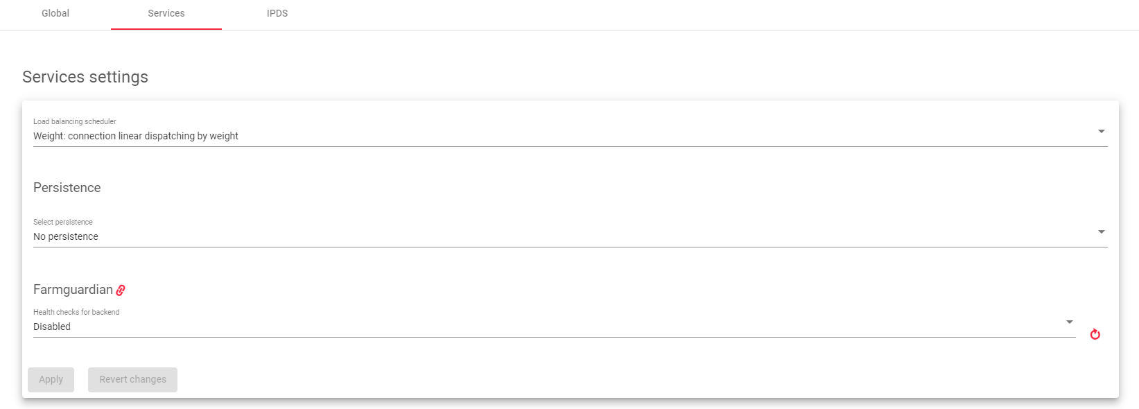
Load balancing scheduler
This field specifies the load balancing algorithm to use to determine which backend server to send requests to. By default, the load balancing algorithm is linear dispatching by weight.
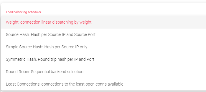
- Weight: Balances connections based on the weight value assigned to each backend. Requests are delivered using a probabilistic algorithm based on the defined weight.
- Source Hash: Balances packets with the same source IP and port to the same backend using a hash scheduler.
- Simple Source Hash: Balances packets with the same source IP to the same backend using a hash scheduler.
- Symmetric Hash: Balances packets with the same source IP and port, and the destination IP and port. This means that it can hash a connection in both directions (during inbound and outbound).
- Round Robin: Balances each incoming connection to a backend, sequentially switching between backends.
- Least Connections: Selects the backend with the fewest active connections to ensure that the traffic load of the active requests is balanced with the traffic load of the most connected available real server.
Persistence
This setting determines whether the service should maintain a connection with the client. By default, no persistence is used.
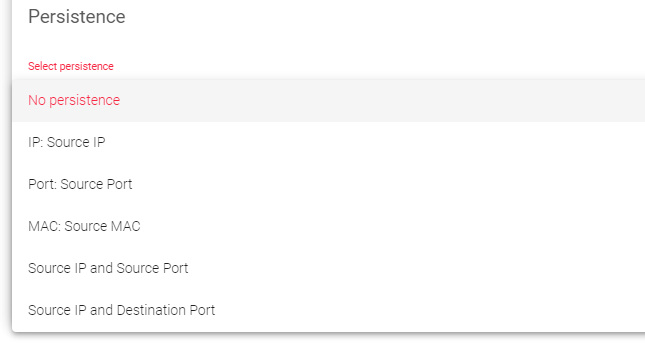
- No persistence: The load balancer will not try to keep the same client connected to the same backend server.
- Source IP: The load balancer will try to keep the same client connected to the same backend server based on the client’s IP address.
- Source Port: The load balancer will try to keep the same client connected to the same backend server based on the client’s port number.
- Source MAC: The load balancer will try to keep the same client connected to the same backend server based on the client’s MAC address.
- Source IP and Source Port persistence: The load balancer will try to keep the same client connected to the same backend server based on both the client’s IP address and port number.
- Source IP and Destination Port persistence: The load balancer will try to keep the same client connected to the same backend server based on both the client’s IP address and the destination port number.
Farmguardian
L4xNAT farms do not have built-in health checks for backends, so you must use Farmguardian to monitor the health of your backends.
One can assign either the Default or Custom advanced health checks to this service.
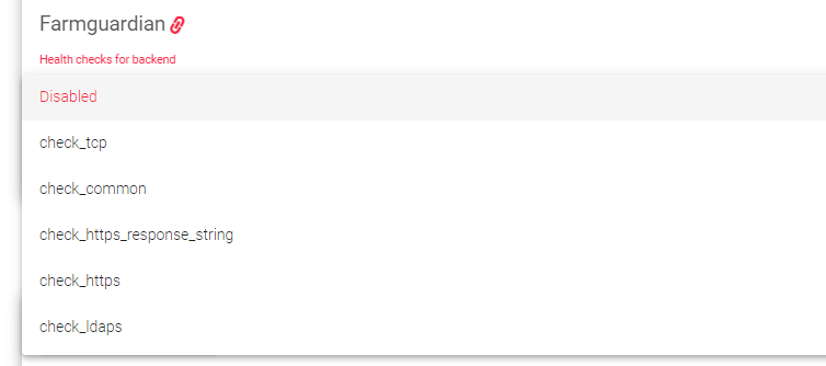
For more information about Farmguardian, see the Monitoring > Farmguardian section. Once you select Farmguardian rule, it will be automatically applied to the farm.
Backends
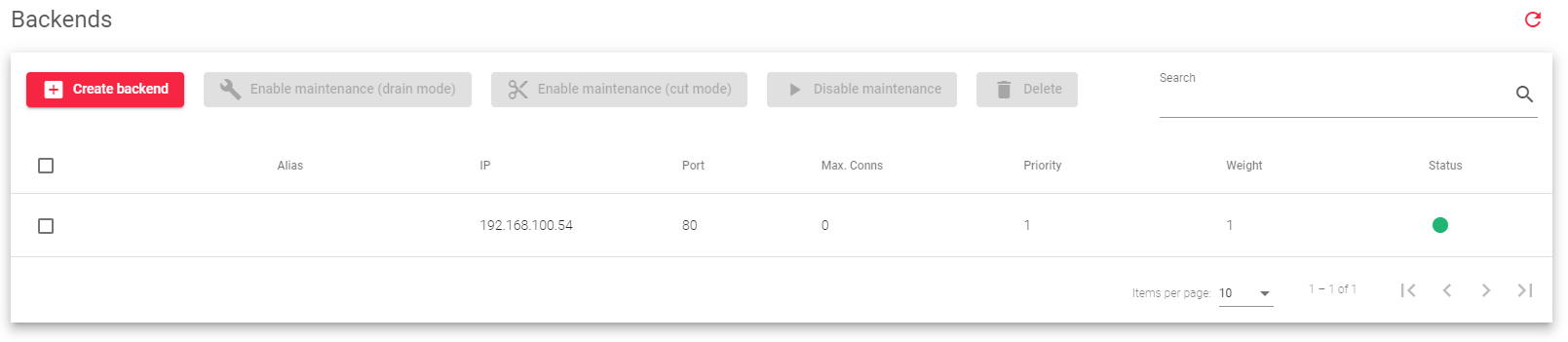
This section allows you to modify or add backends to a farm: Here is a brief description of each field in the table above:
Alias: A list of all available backend aliases.
IP: The IP address of the backend server.
Port: The port number of the backend server.
Max. Conns: The maximum number of connections that can be made to the backend server. If this limit is reached, new connections will be discarded.
Priority: A value that determines how much traffic the backend server receives. Lower values have higher priority. The default priority value is 1. When a backend server fails, its priority is increased by 1. When the backend server comes back online, its priority is decreased by 1. Active backend servers have priority values that are less than or equal to the service priority.
Weight: A value that determines how much traffic the backend server receives when the weight algorithm is selected. This value determines how preferable the backend server is compared to other backend servers. This field allows integer values greater than or equal to 1 (lowest value).
Status: This field indicates the availability of a particular backend server, represented by each of these colors:
- Green: The farm is running and all of the backends are available.
- Red: The farm is stopped or unavailable.
- Black: The farm is running, but none of the backends are available.
- Blue: The farm is running, but at least one backend is unavailable.
- Orange: The farm is running, but at least one backend is in maintenance mode.
Therefore, the backend settings allow you to configure how the load balancer distributes traffic to the backend servers.
Backend Actions

Create backend: On clicking this button, we add a new backend to a farm.
Enable Maintenance: This action is available if the backend is up. It puts a real backend server in maintenance mode, so no new connections will be redirected to it.
There are two methods for enabling maintenance mode:
- Drain Mode: Keeps the established connections and persistence if enabled, but will not accept new connections.
- Cut Mode: Directly drops all active connections against the backend, closing any connection between the backend and clients.
Disable Maintenance: This action is only available if the backend is in maintenance mode. It will enable new connections to be forwarded to the backend server again.
Delete: Removes the backend server from the virtual service. If the backend has an alias, the alias will not be deleted.
Edit: Opens the edit form, the same as the add form, to change any backend value.
IPDS Rules for L4xNAT farms
This section allows you to enable IPDS rules. IPDS rules are security rules that can protect your load balancer from attacks such as denial-of-service attacks, and web application attacks.
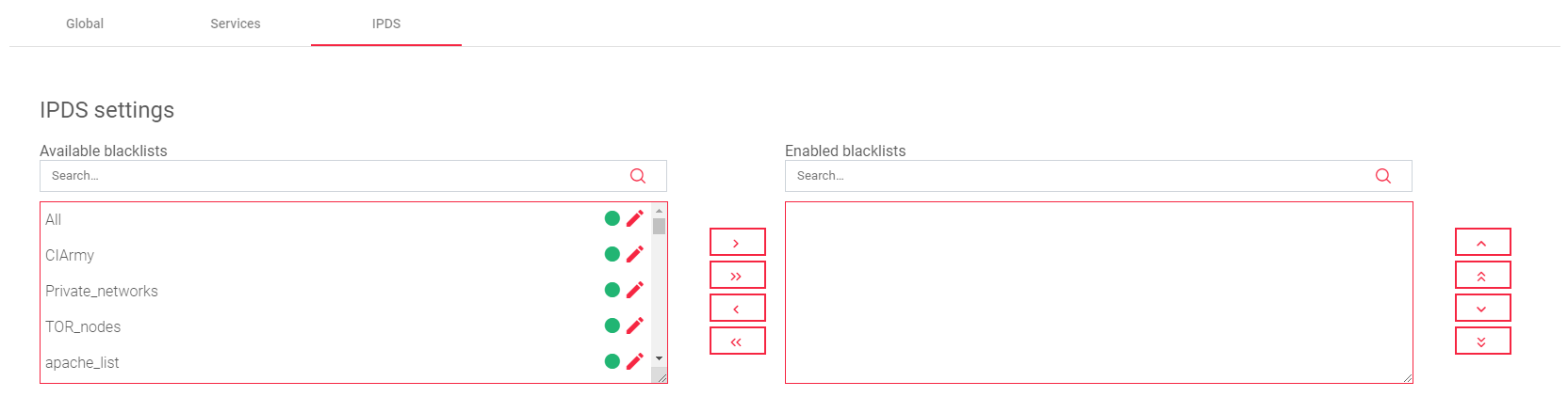
There are four types of IPDS rules: Blacklist, DoS, WAF, and RBL. Each type of rule protects against a different type of attack.
For each type of IPDS rule, there are two tables:
- Available: This table shows all of the available rules of that type.
- Enabled: This table shows all of the rules of that type that are enabled for the selected farm.
One can add or remove rules from the Enabled table by clicking on the Arrows between the two tables.
To change the settings for a rule, click on the Edit icon directly besides the rule.
Important Notice!
One cannot create new IPDS rules from this section. You must create new rules in the IPDS section of the load balancer interface.
Next Article: LSLB | Farms | Update | HTTP Profile
